Beam Design
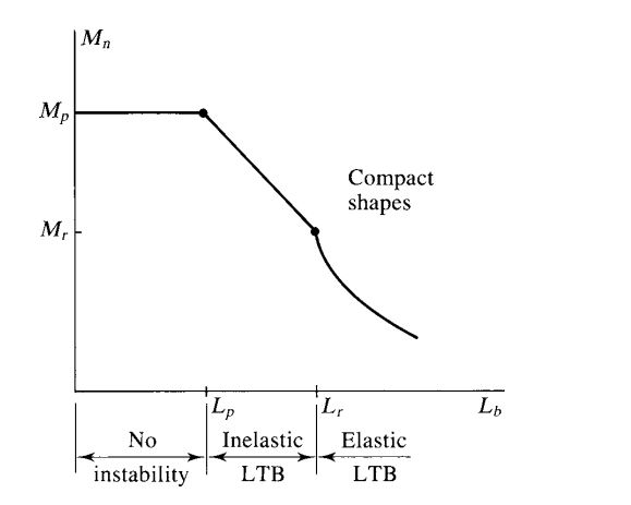
| Note: Beams can fail in reaching plasticity, due to lateral torsional buckling, flange buckling, or web buckling |
| Beams shapes are divivded in 3: compact, non-compact, and slender |
| Yield Stress Fy | Elastic Modulus E |
| Flange Width bf | |
| Flange thickness tf |
| λ = | {{Cf()}}, | λp = | {{Cfp()}}, | λr = | {{Cfr()}} |
| Check Flange Type | {{CST()}} |
| Height of Web h | |
| Web Thickness tw | |
| Web Type | {{CW()}} |
| Check Web Type | {{CWT()}} |
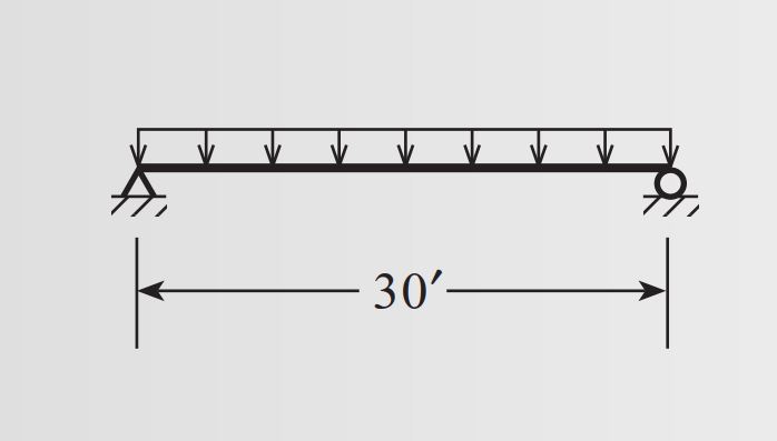
| Applied Uniform Dead Load wd | |
| Applied Unifrom Live Load Wl | |
| Beam Length L | |
| Max Applied Moment Mu | {{Mua()}} kip-ft |
| Section Modulus Z | |
| Nominal Flexural Strength Mn | {{Mn()}} kip-ft |
| Applied Moment Mu | |
| Design Strength | {{fiMn()}} kip-ft |
| Section Check | {{fiMnCheck()}} |
| Unbraced Length Lb | |
| Radius of Gyration rx or y | |
| Inelastic lenghth Lp | {{Lp()}} ft |
| Weak Axis Radius of Gyration | |
| Section Modulus Sx | |
| Polar Moment of Inertia J | |
| Elastic length Lr | {{Lr()}} ft |
| Weak Axis Moment of Inertia Iy | |
| Warping Constant Cw | |
| Cb | |
| Check Elastic/Inelastic LTB | {{CheckEI()}} |
| Inelastic Nominal Moment φMn | {{Mni()}} kip-ft |